Please Choose Your Language

Views: 0 Author: Site Editor Publish Time: 2026-10-23 Origin: Site

Inefficient power distribution is a silent financial drain. Every year, industrial and commercial facilities hemorrhage thousands of dollars through unoptimized electrical systems. Facility managers often miss this entirely. Selecting the wrong equipment leads to excessive heat generation. It causes massive energy waste. Ultimately, it results in premature equipment failure. But you can stop this thermal degradation. By specifying a highly efficient oil immersed power transformer, facility engineers secure a durable solution for minimizing these losses. This guide walks you through the exact technical specifications, design factors, and material choices required to select the perfect unit tailored to your energy system.
Understand Your Losses: Distinguishing between core no-load waste and copper load waste is the foundational step to optimizing overall efficiency.
Material Matters: High-grade silicon steel or amorphous metal cores combined with pure copper windings drastically reduce energy waste.
Cooling Equals Efficiency: Proper cooling mechanisms maintain optimal internal temperatures and prevent heat-induced power degradation.
Sizing is Critical: Oversizing or undersizing your equipment leads to poor power factor optimization and unnecessary baseline energy consumption.
Long-Term ROI: Investing in a well-designed liquid-filled unit yields significantly lower maintenance costs and higher reliability compared to standard dry-type alternatives.
To effectively prevent electrical waste, you must understand the underlying physics. Recent industry analyses reveal a sharp shift in global energy procurement. Grid modernization and strict carbon emission mandates are forcing plant engineers to aggressively target baseline inefficiencies. Energy auditors no longer ignore transformer losses. With modern grids demanding continuous uptime, even a minor drop in efficiency compounds into massive financial penalties over a fiscal year. Upgrading legacy systems to optimized liquid-filled units is now a primary strategy for future-proofing industrial infrastructure.
Think about your plant during a complete holiday shutdown. No machines are running. Yet, your energized transformer still consumes power. We call these no-load or core losses. They stem from hysteresis and eddy currents within the core metal. Since this waste happens 24 hours a day, stopping it is a top priority for any serious energy strategy.
In contrast, load losses fluctuate directly with your facility demand. Often referred to as copper losses, these occur in the primary and secondary windings when power is actively drawn by your machinery. Driven by the formula of current squared times resistance, these losses manifest entirely as heat. As your facility draws more current during peak production hours, the internal resistance of the winding material naturally converts valuable electrical energy into useless thermal output.
Beyond the primary core and windings, minor efficiency drops occur through stray and dielectric losses. Leakage fluxes induce unwanted currents in the surrounding metal tank and structural components. Furthermore, insulating materials absorb a small fraction of energy. Utilizing premium-grade insulating fluids mitigates these issues, maintaining a smooth and unobstructed flow of power.
When engineering a new substation or upgrading an industrial plant, procurement teams often debate between dry-type and liquid-filled solutions. From a practical engineering standpoint, the thermal dynamics heavily favor liquid-filled units for heavy-duty applications.
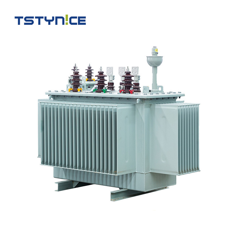
Liquid cooling is inherently superior to air cooling. In a dry-type unit, ambient air is the only medium available to carry heat away from the core and windings. Conversely, an industrial oil immersed transformer utilizes specialized dielectric fluids circulating through internal components. This fluid absorbs heat rapidly. It transfers thermal energy to external radiators much more efficiently than air ever could. This prevents the dangerous temperature spikes that increase electrical resistance.
Evaluating the total cost of ownership over a 30-year lifecycle reveals a clear winner. To make the selection process easier, look at this core comparison of operational metrics.
Performance Metric | Oil Immersed Transformer | Dry-Type Transformer |
|---|---|---|
Cooling Efficiency | Excellent. Liquid rapidly transfers heat to radiators. | Limited. Relies solely on ambient air convection. |
Energy Loss Profile | Very Low. Optimized for continuous heavy loads. | Moderate to High under peak load conditions. |
Overload Capacity | High. Fluid thermal mass absorbs temporary spikes. | Low. Prone to rapid overheating during overloads. |
Operating Environment | Ideal for harsh outdoor and heavy industrial sites. | Restricted mostly to clean indoor environments. |
Lifespan Expectancy | 25 to 30 plus years with standard maintenance. | 15 to 25 years depending on thermal stress. |
Selecting the correct unit is never a matter of guessing. It requires a precise alignment of facility demands with hard equipment specifications. A mismatch here will cripple a plant operational budget.
I often see sprawling manufacturing plants operating at 80 percent capacity with poorly sized substations. If a procurement manager signs off on an undersized unit, the equipment runs dangerously hot. Insulation breaks down fast, and catastrophic failure becomes inevitable. On the other hand, gross oversizing means you pay a premium for massive no-load losses you never use. Accurately calculating your peak and continuous power demands is essential to finding the exact KVA rating that balances reliability with efficiency.
Instead of relying on abstract concepts, use hard data for your next procurement cycle. For medium voltage distribution, a standard 20kV 22kV oil immersed transformer must offer specific performance metrics. Look for a rated capacity spanning 50kVA to 3150kVA to perfectly match your peak demand. The vector group must align with your existing infrastructure, typically Dyn11 or Yyn0. Furthermore, insist on an impedance voltage strictly between 4 and 6 percent. This exact setup prevents severe voltage drops while keeping fault currents manageable. Additionally, ensure the tap changer offers a regulation range of plus or minus 2 times 2.5 percent to maintain stable output voltage.
The insulating fluid does more than just prevent arcing. It is the lifeblood of the cooling system. Mineral oil remains the industry standard, offering excellent thermal conductivity. However, modern environmental trends are pushing some facilities toward ester-based fluids. These advanced fluids offer higher flash points and superior moisture tolerance, directly impacting the unit ability to maintain peak efficiency over decades of use.
The internal construction of the unit dictates its baseline efficiency. The global shift towards highly optimized magnetic materials is fundamentally reshaping how engineers specify electrical infrastructure.
The traditional standard is cold-rolled grain-oriented silicon steel, which performs admirably. Yet, for facilities obsessed with minimizing energy waste, upgrading to an amorphous alloy core is a game-changer. The random atomic structure of amorphous metals allows for incredibly easy magnetization and demagnetization. Integrating an amorphous core slashes no-load core losses by up to 70 percent, delivering massive continuous energy savings.
While aluminum windings are lighter and cheaper upfront, they simply cannot match the electrical conductivity of pure copper. Copper offers significantly lower electrical resistance. Because load losses are directly tied to resistance, investing in copper windings translates to a drastic reduction in the heat generated during heavy production cycles. This ensures more power reaches your machinery and less is lost to the surrounding air.
Temperature control and electrical efficiency are inextricably linked. Allowing a unit to overheat is the absolute fastest way to bleed energy and money.
Cooling classes dictate how the unit handles thermal stress. ONAN, meaning Oil Natural Air Natural, relies entirely on natural convection. Hot fluid rises, cools in the radiators, and sinks. It is highly reliable and requires no moving parts. However, for facilities with intense peak loads, ONAF, meaning Oil Natural Air Forced, introduces external fans to aggressively cool the radiators. Selecting the right cooling method based on your installation environment ensures internal components remain within their optimal temperature threshold.
The physics are straightforward. As the temperature of a conductive material rises, its electrical resistance increases. Increased resistance creates a vicious cycle of even more heat and higher power loss. Efficient liquid cooling breaks this cycle by rapidly stripping heat away from the active components. This keeps the resistance low and the electrical transfer highly efficient.
Modern industrial loads are incredibly complex. A high-quality electrical unit must be designed to handle these harsh realities without degrading.
Today manufacturing floors are packed with Variable Frequency Drives, LED lighting networks, and automated robotics. These non-linear loads introduce harmonic distortion back into the electrical system. This generates excessive, localized heat within standard windings. A properly specified high-efficiency oil immersed transformer features specific K-factor ratings and reinforced winding designs to mitigate these harmonic losses, preventing thermal damage.
Efficiency means nothing if the unit fails after five years. Structural design elements are vital. Look for heavy-duty tank construction, advanced sealing mechanisms to prevent oxygen ingress, and integrated moisture management systems. These physical safeguards ensure the internal fluid remains pure and the core stays protected. This allows the equipment to maintain its day-one efficiency over a rigorous 30-year lifespan.
Procuring heavy electrical equipment is a long-term partnership. Off-the-shelf solutions rarely provide the exact thermal and electrical characteristics needed to truly minimize waste in a complex facility.
Navigating the regulatory landscape requires deep expertise. It is imperative to source equipment that exceeds stringent global energy efficiency standards, such as IEEE, IEC, and local Department of Energy regulations. A reputable manufacturer guarantees their units are fully compliant and rigorously tested before deployment.
Every facility possesses a unique load profile. Working directly with an experienced manufacturer allows you to customize core materials, winding configurations, and cooling mechanisms to match your exact site requirements. This bespoke approach ensures you never pay for unnecessary capacity while achieving the lowest possible power loss.
Preventing power losses is an engineering strategy requiring careful selection of core materials, winding types, and cooling specifications. A highly efficient, properly sized unit pays for itself through significantly reduced electricity bills and minimized maintenance downtime. If you are ready to optimize your facility energy distribution, stop losing money to heat. Evaluate your current load, match it against the parameters discussed, and select a product that guarantees efficiency. Visit https://www.tstynice.com to explore our extensive catalog of high-efficiency solutions and find the exact specifications required for your next successful project.
The most effective way to reduce core losses is by upgrading the internal magnetic materials. Utilizing high-quality cold-rolled grain-oriented silicon steel or advanced amorphous metal cores significantly lowers hysteresis and eddy currents. This ensures minimal energy is wasted when the unit is energized.
Generally, oil immersed units are far more efficient for high-capacity, outdoor, and heavy industrial applications. Their superior liquid cooling capabilities allow for better heat dissipation. This keeps internal resistance low and reduces overall load losses compared to air-cooled dry-type alternatives.
When properly specified and maintained, these robust units are designed for extreme longevity. With routine fluid analysis and diligent load management, they typically operate efficiently for 25 to 30 years, and often much longer in controlled environments.
The insulating fluid acts as the primary heat transfer medium. High-grade dielectric oils boast superior thermal conductivity, meaning they pull heat away from active windings much faster. By keeping the internal components cooler, electrical resistance remains low, which directly minimizes load losses.
Power factor optimization refers to selecting a unit with the precise impedance and load capacity to match your facility demands. This ensures the electrical system utilizes active power efficiently to perform actual work, without drawing excessive and wasteful reactive power from the grid.
In highly optimized industrial systems, total power loss should remain below 1 to 2 percent of the total kVA rating at full load. Exceeding this threshold usually indicates outdated core materials, poor cooling, or severe equipment undersizing.
Transformers achieve peak efficiency when operating between 50 and 70 percent of their maximum load capacity. Continuous operation near 100 percent drastically increases copper resistance, which generates excess heat and exponentially multiplies energy waste.