

Views: 0 Author: Site Editor Publish Time: 2025-10-09 Origin: Site
In the intricate web of modern infrastructure, few components are as fundamental yet as overlooked as the transformer. These silent workhorses form the critical backbone of our electrical power systems, enabling the efficient transmission and distribution of electricity over vast distances. While single-phase transformers are common in residential applications, the industrial and commercial world runs on three-phase power. At the heart of this system is the Three Phase Oil Immersed Power Transformer, a robust and reliable piece of engineering designed to handle immense power levels. This article delves into the construction, operation, and, most importantly, the vital connection schemes of these transformers, providing a comprehensive understanding for engineers, technicians, and anyone curious about the flow of power that fuels our world.

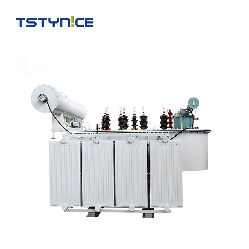
A three-phase transformer is essentially a single, static device that handles the three phases of an electrical system simultaneously. Its construction is a marvel of electrical and mechanical engineering, designed for maximum efficiency, durability, and safety. The most common and powerful type, especially for high voltage applications, is the Three Phase Oil Immersed Power Transformer. Its construction can be broadly divided into two main types based on the arrangement of the core and windings: the core type and the shell type.
The core type design is more prevalent for large power transformers. It features three limbs, with each phase’s low voltage (LV) and high voltage (HV) windings concentrically placed on a separate limb. This design offers better cooling and easier access to the windings for maintenance. The shell type, on the other hand, has a central limb surrounded by windings, with the magnetic flux path encircling the windings like a shell. While offering a shorter magnetic circuit and better mechanical protection, it can be more complex to manufacture and cool.
Regardless of the core design, the components of a modern Three Phase Oil Immersed Power Transformer are meticulously crafted to work in harmony:
Magnetic Circuit: The core is constructed from thin, laminated sheets of silicon steel. This lamination is crucial to minimize eddy current losses, a key component of the no-load loss. The core’s job is to provide a low-reluctance path for the magnetic flux generated by the windings.
Electrical Circuit: This consists of the HV and LV windings, typically made of copper or aluminum. These coils are carefully insulated from each other and from the core. The design of these windings directly impacts the transformer’s load loss and short-circuit impedance.
Insulating Oil: This is the lifeblood of an oil-immersed transformer. The oil serves a dual purpose: it provides superior electrical insulation between live parts and the grounded tank, and it acts as an efficient cooling medium, transferring heat from the core and windings to the cooling radiators.
Conservator Tank: This is an auxiliary tank mounted above the main transformer tank. It allows for the expansion and contraction of the insulating oil due to temperature changes, preventing the main tank from being pressurized.
Breather: The breather, often filled with silica gel, is connected to the conservator. Its function is to ensure that the air entering the conservator is dry, preventing moisture from contaminating the oil and degrading its insulating properties. This is critical for maintaining long-term sealing performance.
Cooling System: The transformer tank is equipped with radiators or fins to dissipate heat. Cooling methods are classified by standards like ONAN (Oil Natural Air Natural) for smaller units and ONAF (Oil Natural Air Forced) for larger, more demanding applications, where fans are used to increase airflow over the radiators.
The entire assembly is housed in a robust steel tank designed to withstand pressure and environmental factors, ensuring the transformer’s reliable operation for decades.
The operating principle of a three-phase transformer is rooted in Faraday’s law of electromagnetic induction. When an alternating current flows through the primary winding, it creates a time-varying magnetic flux in the magnetic circuit (the core). This changing flux then induces a voltage in the secondary winding. The ratio of turns between the primary and secondary windings determines the voltage transformation ratio.
In a three-phase system, this process occurs simultaneously on three separate sets of windings, each energized by a phase of the three-phase AC supply, which are 120 degrees apart. This creates a balanced, rotating magnetic field within the transformer core, allowing for a smooth and constant power transfer. The interaction between the magnetic circuit and the electrical circuit is what facilitates the stepping up or stepping down of voltages, making long-distance power transmission feasible and efficient.
A key aspect of a transformer’s performance is its losses, which are critical metrics for any Three Phase Oil Immersed Power Transformer. These are primarily categorized as:
No-Load Loss (Core Loss): This loss occurs in the core whenever the transformer is energized, regardless of whether it is supplying power to a load. It consists of hysteresis loss (due to the magnetization and demagnetization of the core material) and eddy current loss (due to circulating currents induced in the core laminations). Modern transformers use high-grade grain-oriented steel to minimize these losses.
Load Loss (Copper Loss): This loss is proportional to the square of the load current flowing through the windings (I⊃2;R loss). It is the heat generated due to the resistance of the winding conductors.
Another critical parameter is the short-circuit impedance, expressed as a percentage. This value represents the internal impedance of the transformer and is vital for several reasons: it limits the fault current during a short circuit, and it must be matched for transformers operating in parallel to ensure proper load sharing. Furthermore, strict control over temperature rise is essential, as excessive heat degrades the insulating oil and winding insulation, shortening the transformer’s lifespan.
The most critical aspect of deploying a three-phase transformer is understanding its connection methods. The primary and secondary windings of a Three Phase Oil Immersed Power Transformer can be connected in two fundamental configurations: the Wye connection (also known as Star) and the Delta connection. The choice of connection has profound implications for system voltage, current, grounding, and the handling of harmonics.
In a wye connection, one end of each of the three windings (either primary or secondary) is connected to a common point called the neutral point. The other ends of the windings connect to the three line conductors.
Voltage Relationship: The line voltage (voltage between any two line conductors) is equal to the square root of three (√3) times the phase voltage (voltage across a single winding).
Current Relationship: The line current (current in a line conductor) is equal to the phase current (current through a single winding).
Advantages:
Provides a neutral point, which can be grounded for system stability or used to supply single-phase loads at a lower voltage.
Better suited for handling unbalanced loads because the neutral point can carry the resulting neutral current.
Allows for two different voltage levels (e.g., 208V/120V or 11kV/6.35kV) from the same transformer.
In a delta connection, the windings are connected in a closed-loop triangle, with the end of each winding connected to the start of the next. The line conductors are tapped from the three junction points of the windings.
Voltage Relationship: The line voltage is equal to the phase voltage.
Current Relationship: The line current is equal to the square root of three (√3) times the phase current.
Advantages:
More stable under unbalanced loads as the circulating current within the delta loop helps balance the phases.
Traps third-order harmonics (triplen harmonics) within the delta loop, preventing them from propagating into the power lines.
Generally more economical for high voltage, low current applications because the winding insulation only needs to withstand the phase voltage, which is lower than the line voltage in a wye system.
The Three Phase Oil Immersed Power Transformer is more than just a piece of equipment; it is a cornerstone of modern civilization, enabling the reliable and efficient delivery of electrical energy. Understanding its construction reveals a symphony of materials and design principles aimed at achieving optimal performance and longevity. Grasping its working principles connects the abstract laws of electromagnetism to the tangible flow of power in our cities and industries.
However, the true mastery of this technology lies in understanding its connections. The choice between wye connection and delta connection is not arbitrary; it is a strategic decision that impacts system voltage, current handling, fault management, and the mitigation of harmonics. The vector group provides a standardized language to describe these configurations, ensuring compatibility and safety across the grid.
As we look to the future, the role of these transformers is evolving. The latest trends involve integrating smart sensors and IoT technology to monitor parameters like oil quality, dissolved gas analysis, and temperature rise in real-time. This predictive maintenance approach, combined with a continuous push for designs with lower no-load loss and load loss, is making the power grid smarter and more sustainable. Despite these advancements, the fundamental principles of the Three Phase Oil Immersed Power Transformer remain unchanged, a testament to its enduring and vital role in powering our world.


